RF Front-End Mezzanines
Mezzanines provide analogue front-ends (AFEs) for the DACs on Sayma. Same connectors as in FMC standard were used, but these AFEs are not compatible with FMC standard. Connectors are swapped between carrier and AFE to avoid insertion of incompatible FMC module.
There are several kinds of signals routed to AFE:
16 signals from the RTM FPGA - 3.3V LVCMOS voltage levels
8 pairs of LVDS signals from the RTM FPGA
12 pairs of LVDS signals from the AMC FPGA
2 I2C buses - 3.3V LVCMOS voltage levels
GTP link from the RTM FPGA
4 differential analog channels from DAC
differential reference clock
Each AFE is supplied with several analog and digital power supplies:
P12V0A
P6V0A
P2V5F
P3V3
N12V0A
N6V0A
P3V3MP
See Maximum power draw for each Mezzaninne.
TestMod
Simple mezzanines designed for thermal and connectivity testing, and to serve as a template for other mezzanine designs.
Todo
image
Design repository is here, production files are here.
Design reporistory contains 4 projects that were used for prototyping different aspects of AFE design:
FMC Breakout - breaks out all FMC HPC signals to FMC LPC (LPC signals) and VHDCI connector (HPC signals), with exception of gigabit links
TestMod_SEAx - “the” Testmod
routes DAC differential signals to balun to SMA connectors
routes ADC signals to balun to ADC pins on FMC connector
routes MEZZ_IO signals to I2C GPIO extenders
routes LVDS signals to 30-pin connector
load can be manually enabled on each power supply rail on connector
has additional SMA and MMCX connectors to test trace impedance
TestMod_SEAx_Baseboard - simpler version of TestMod_SEAx, with just SMA connectors for 8 analog signals and 30-pin connector for LVDS signals
Test_SEAx - board with mating connector for TestMod_SEAx and TestMod_SEAx_Baseboard, which was used to check signal properties of the connector
BaseMod
BaseMod is a base-band input/output mezzanine. Design repository is here, production files are here.
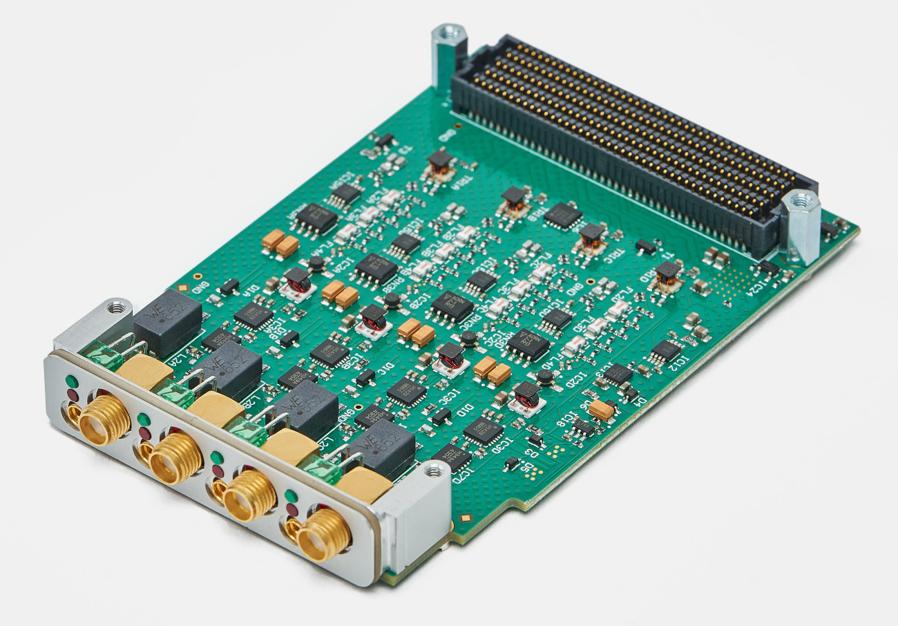
Outputs
BaseMod provides four independent RF outputs, featuring:
Bandwidth: 10MHz - 4GHz (upper frequency is limited by several different components)
Max output power: ?dBm (limited by ?).
Output filters: either 3 Mini-Circuits FV1206 series filters, or a user-definable discrete 9-pole discrete-element filter using 0402 components.
Low phase noise amplifier: Mini-Circuits ERA-4XSM+, 14.2dBm gain at 1GHz.
Digitally programmable attenuator: HMC542BLP4E; 0dB to 31.dB in 0.5dB steps; controllable in real-time.
Fast, high-isolation RF switch: HMC349LP4C; 67dB isolation at 1GHz; controllable in with real-time control.
Power detector: AD8363ACPZ on switch “off” port for monitoring and power levelling.
Optional isolation of output grounds: to avoid ground loops, achieved by fitting capacitors and washers.
Inputs
BaseMod provides four inputs which are routed to LTC2324 ADC. ADC and input channel design are the same as in Sampler EEM module.
Bandwidth: DC-200kHz
Input ranges: ±10mV, ±100mV, ±1V, ±10V
Fully differential inputs: input signal routed to differential amplifier
Filters: Common-mode and differential mode filtering of RF interference for optimum DC precision
Input protection: diodes between each input and the supply rails for maximum ruggedness
MixMod
MixMod is a planned up-converting mezzanine, using an analogue IQ mixer to mix the input and output RF signals with a LO supplied by Sayma.
Design repository is here, though it wasn’t updated for Sayma v2.0. Check issues in that repository for remaining problems in schematics. Initial specifications are here.
MixMod should provide a single RF output between 2.5GHz and 3.5GHz, produced by mixing two DAC channels with a LO supplied by Sayma. Other than the IQ mixer, the output signal-chain is identical to BaseMod.
Mezzanines Mechanical Specification
Board size
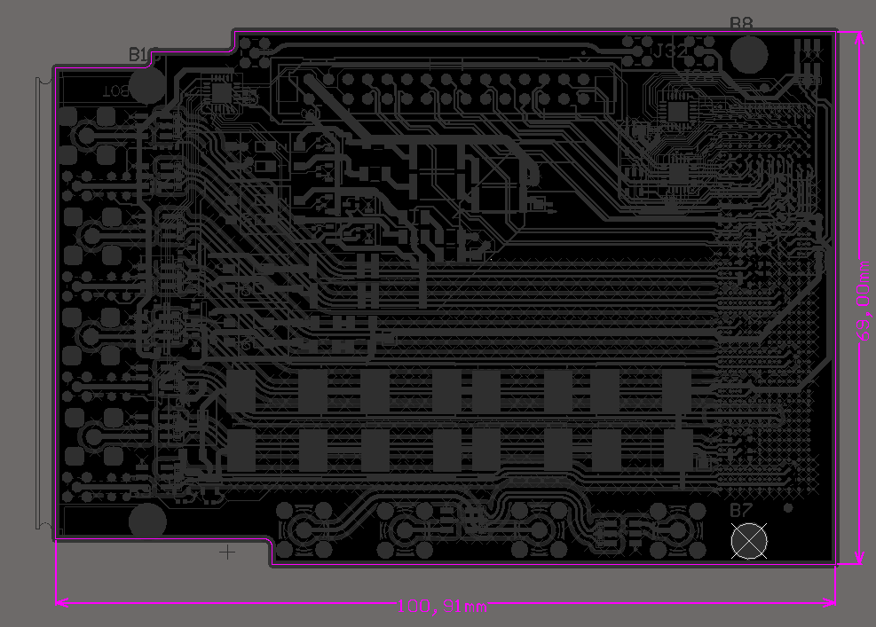
Mezzaninne dimensions
Mounting holes: There are four mounting holes fi 2.7mm for M2.5 screws.
For exact mechanical drawings visit TestMod repository, where source files are located.